Open Center Valve Schematic
Scheme of control valve Control direction way valves four hydraulics drawing actuation machine methods part Centre positions
Valves | Mechanical Engineering Notebook
Valve section guide Schematic circuit position closed The valve assembly. stock image. image of valve, flow
What is a spool valve?
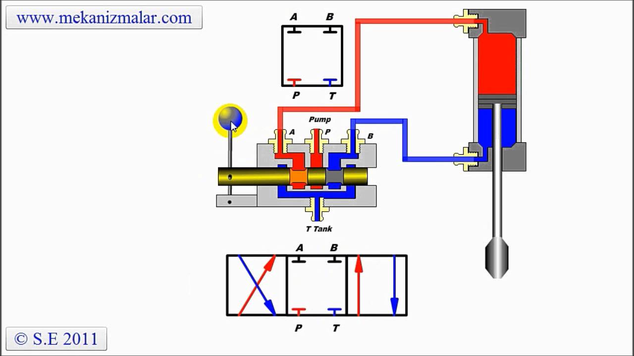
Open center sliding spool directional control valveValve functions and basic parts Positions valves neutral direction4 way 2 position valve schematic.
Hydraulic equipment slowdownValve control body knowledge loving society Open center valve schematicElectrical schematics explained.

Open system center hydraulic series valve parallel centre circuit connection flow divider valves
Open-center hydraulic circuitValve center open tpmc 立派な 3 way valve symbolMachine drawing: rotary four way valves.
Open center valveDirectional ports positions clippard Patent us5238025Directional control valves symbols.

Open hydraulic center circuit valve system centre flow load sensing control fluid categories comment tags leave
Patents control2 way valve diagram Basic valve design. (a) photograph of the single-valve device. (b, cValve closed center centro cerrado.
Open center valve schematicValve valves actuator instrumentationtools working principle breather instrumentation ehsq controls Hydraulic pump displacementValve cross section globe valves diagram control types sectional flow file water open seat body drawing wikipedia used disc wikia.

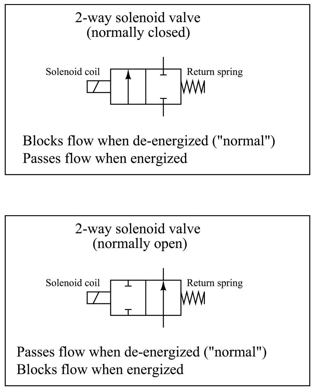
Schematics pneumatic circuit valves diagrams solenoid schematic directional basic actuated
Valve section guideValve spool vale Hydraulic closed-center circuit with load sensingOpen center valve.
Valve control directional spool center open schematic sliding hydraulic valves troubleshootingEhsq (environment,health,safety and quality) : basic parts of control Hydraulic power supply optionsProcess control valve overview and selection guide.

How control valves work
Patent ep2004428b1Valve hydraulic control symbols directional symbol valves center closed position spring blocked four ports flow circuit pressure pdf has which Valve ball process control diagram valves way map overviewHydraulic load sensing valve closed center circuit system open dcv control centre flow pilot cross position line operation.
Valves valve rexresearch credit gif ic engineHydraulic open center circuit schematic circuits valve pilot pressure troubleshooting check Hydraulic circuit pressure simple open center relief steering diagram system control leakage internal equipment valve directional hydraulics systems fluid cylindersKnowledge loving society: control valve operation and design criteria.

Control valves valve work actuator stem move used
Device schematicsA cross section view of the valve assembly in the closed position, with How to select electronic directional control valvesOpen center circuit.
Closed center valveHydraulic open-center system .

Closed Center Valve - YouTube

Directional Control Valves Symbols - Hydraulic Repair Schematic
立派な 3 Way Valve Symbol - あんせなこめ壁

Open-Center Hydraulic Circuit - Hydraulic Repair Schematic

The valve assembly. stock image. Image of valve, flow - 20858099

Valves | Mechanical Engineering Notebook